Unlocking the Secrets of Planar Magnetics Datasheets: A Junior Engineer's Guide to Key Metrics
 Navigating a datasheet can feel like deciphering an ancient code, especially when you're just starting out in power electronics. As a junior engineer, you might be tasked with selecting components for a high-frequency converter or an EV charger, and suddenly terms like "leakage inductance" and "thermal resistance" are staring back at you. But fear not, these documents are your roadmap to building efficient, reliable systems. In the realm of planar magnetics, datasheets from leaders like Payton Group offer a wealth of insights tailored to modern demands for compactness and performance.
With over 38 years in the game, Payton Group crafts custom planar transformers and inductors that excel in high-power, low-profile applications. This guide is designed to help you, the aspiring power engineer, break down a typical planar magnetics datasheet. We'll focus on critical metrics like leakage inductance and thermal resistance, using real examples to make it practical. By the end, you'll feel confident interpreting these specs and applying them to your designs. Let's dive in.
Why Planar Magnetics? A Quick Primer for Newbies
Before we tackle the datasheet, let's set the stage. Planar magnetics differ from traditional wire-wound components by using flat copper traces on multi-layer PCBs or laminates, sandwiched around a planar core. This design shines in high-frequency operations (typically 50 kHz to 3 MHz), where it delivers superior efficiency, lower EMI, and better heat management.
Why does this matter for datasheets? Planar tech inherently reduces parasitics and improves repeatability, so the specs you'll see reflect these advantages. For instance, Payton's planar transformers can achieve efficiencies of 97-99%, making them ideal for space-constrained setups like aerospace or industrial converters. Traditional datasheets might show higher losses or bulkier dimensions, but planar ones emphasize power density, often up to 25 kW per component.
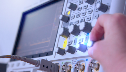
As a junior, start by scanning the datasheet's overview section. It usually includes the model (e.g. Payton SIZE 551), power range, frequency recommendations, and supported topologies like full bridge or flyback. This gives context: Is this component suited for your 200 kHz DC-DC converter?
Breaking Down the Datasheet Structure
A well-organized planar magnetics datasheet, like those from Payton, typically follows a logical flow. Here's how to approach it:
- General Description: Outlines the component's purpose, such as "high efficiency, low EMI for high-power applications." Note the operating temperature range (-40°C to +130°C is common) and isolation voltage (up to 4 kVrms).
- Electrical Specifications: core metrics like inductance, resistance, and currents.
- Thermal and Mechanical Data: crucial for reliability in real-world use.
- Dimensions and Mounting: ensures it fits your PCB layout.
- Application Notes: Payton often includes tips on cooling or custom configurations.
Pro tip: use bullet points or tables in datasheets to your advantage, they make quick comparisons easy. Always check for footnotes or references to standards like UL or MIL-STD.
Decoding Leakage Inductance in Planar Context
Leakage inductance is one of those metrics that can trip up beginners, but it's pivotal in switching power supplies. Simply put, it's the portion of the magnetic flux that doesn't couple between primary and secondary windings, acting like an unwanted inductor in series. High leakage can cause voltage spikes, ringing, and efficiency drops - bad news for high-frequency designs.
In planar magnetics, leakage is minimized thanks to the interleaved, flat windings and tight coupling. Payton's designs often boast leakage inductance less than 0.2% of the primary inductance for un-gapped cores, which is a game-changer compared to traditional transformers where it can be 10 times higher. This low value reduces EMI and allows for softer switching, extending component life.
How to read it on a datasheet? Look for it under "Parasitic Parameters" or "Electrical Specs," often listed in μH or as a percentage. For example, in Payton's T80 AC transformer, the primary leakage inductance is specified at 100 nH max. If your design involves resonant converters, calculate the impact: Leakage inductance affects the resonant frequency (f_r = 1 / (2π √(L_leak * C)). A low value like Payton's means more predictable performance and fewer snubbers needed.
Pro tip: If the datasheet doesn't list it explicitly (some custom ones require calculation), contact the manufacturer. Payton's team can provide AL values (nH/turn²) to help you model it. In practice, for a 400W full-bridge setup using Payton's Size 50, low leakage ensures minimal energy loss during commutation.
Mastering Thermal Resistance: Keeping Things Cool
Thermal management is where many designs falter, leading to derating or failures. Thermal resistance (often called thermal impedance in datasheets) measures how effectively heat flows from the component's hot spot to the ambient or heatsink, in °C/W. A lower value means better cooling, crucial in planar magnetics, where the flat design spreads heat evenly across the PCB surface.
Unlike traditional magnetics with hotspots in windings, planar ones leverage short thermal paths for superior dissipation. Payton's datasheets break it down by cooling method:
- Natural cooling: Higher resistance, e.g., 65 °C/W for Size 14.
- Blowing air (3 m/s): Around 4 °C/W for larger sizes like 551.
- Heatsink (one side): 2.6 °C/W; two sides: 1.3 °C/W.³
To interpret: Hot spot temperature = Ambient (or heatsink) temp + (Thermal resistance × Power losses). For Payton's Size 551 in a 2596W application, with 38W losses and a 65°C heatsink (one side, 2.6 °C/W), hot spot hits about 145°C, within the +130°C limit.
Why focus on this? Poor thermal design shortens lifetime via insulation degradation. Payton's application note AN-001 explains conduction cooling: Attach the planar to a chassis with thermal grease for optimal results. In an industrial power supply, this could mean running at 98% efficiency without fans, saving space and noise.
Other Essential Metrics to Watch
Don't stop at leakage and thermal. A comprehensive read covers these too:
- Inductance and AL Value: primary/secondary inductance in μH; AL (nH/turn²) for custom winding calcs. Example: Payton's Size 270 inductor at 300 μH ±10/-20%.
- DC Resistance (DCR): measures winding losses, in mΩ. Lower in planar due to wide traces—e.g., 0.09-0.8 mΩ in SMT models.
- Efficiency and Losses: often 97-99%, with total losses listed (e.g., 4.2W for Size 50 at 400W). Calculate: Efficiency = (Output power / (Output + Losses)) × 100.
- Power Density and Dimensions: Planar excels here - e.g., Size 20 handles 10-40W in 15x16x5-8mm, weighing 4-6g.
- Currents and Volt-Sec Product: RMS/peak currents; volt-sec for saturation avoidance. In Payton's T20 DC, 40W at 36.2 V-μsec.
Cross-reference with your circuit sims, tools like LTspice can model these for validation.
Practical Tips for Junior Engineers
Reading a datasheet isn't passive; it's interactive. Here’s how to make it work for you:
- Start with Requirements: list your project's frequency, power, and space constraints. Match to the datasheet's recommended range.
- Use Tables for Comparison:
Metric Typical Planar Value (Payton) Why It Matters Leakage Inductance <0.2% of primary Reduces EMI, enables high-freq switching Thermal Resistance 1.3-65 °C/W (cooling dependent) Predicts temp rise, ensures reliability Efficiency 97-99% Minimizes energy waste in green designs Power Density Up to 25 kW/component Fits compact EVs or aerospace - Account for Derating: factor in ambient temp and altitude, Payton's ranges are conservative.
- Seek Custom Insights: Payton's 100% custom approach means datasheets can be tailored. Use their request forms for simulations.
- Common Pitfalls: ignore parasitics at your peril; always verify with prototypes. And remember, planar's repeatability means less variation lot-to-lot.
In a real scenario, like designing a 400W converter, start with Payton's Size 50 datasheet: check leakage for your resonant tank, thermal for cooling needs, and efficiency for overall system performance.
Wrapping Up: From Datasheet to Design Mastery
Mastering planar magnetics datasheets is a stepping stone to becoming a proficient power engineer. By understanding metrics like leakage inductance (kept ultra-low in Payton's designs for clean switching) and thermal resistance (optimized for efficient cooling), you'll avoid common traps and create robust systems. These components aren't just specs on paper, they're enablers for innovative, high-density power solutions in everything from EVs to military gear.
At Payton Group, we're here to support your journey. You can view our Planar solutions or reach out for custom consultations: let's turn those datasheet insights into real-world wins. Keep experimenting, stay curious, and watch your designs soar.