Precision Leakage Inductance Measurement
Why Leakage Inductance Measurement Is So Tricky on Planar Designs
 In a well‑designed planar transformer, leakage inductance is usually well under 1% of the primary inductance, and in many Payton designs it is closer to 0.1-0.2%. That is great for efficiency and tight coupling, but it creates a measurement problem: you are trying to extract a small value on top of a large magnetizing inductance, through fixtures that may add significant parasitic inductance of their own.
For comparison, a conventional wire‑wound transformer might have leakage in the 2-5% range of the primary inductance. Planar technology, especially with interleaved windings, pushes that down by an order of magnitude. Payton’s planar transformer design guide and datasheet metrics guide explicitly discuss this: leakage is a key figure of merit, but only if you measure it correctly and at relevant frequencies.
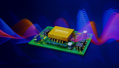
For engineers working on high‑frequency, high‑density designs, like the 15 kW planar transformers Payton showcases for industrial and transportation applications, accurate leakage inductance data feeds directly into LLC tank design, clamp networks, and EMI tuning. That is why getting the lab setup right matters so much.
What Leakage Inductance Really Represents in Planar Magnetics
Physical meaning and design impact
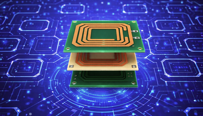
Leakage inductance is the part of the magnetic field that links only one winding instead of coupling between primary and secondary. In equivalent circuit terms, it appears as an extra series inductance on each side of the transformer. In planar designs:
- Very low leakage inductance is essential for high-efficiency forward or flyback topologies that do not want energy stored outside the main core path.
- Controlled, non‑zero leakage inductance can be intentionally used as the series resonant inductance in LLC or as part of a snubber or clamp.
Payton’s planar transformer advantages article notes that planar structures typically achieve much lower leakage inductance than equivalent conventional transformers, thanks to wide cores and interleaved windings. But whether low or intentional, you only benefit if the measured value matches the design intent.
Why planar leakage is hard to measure precisely
Planar leakage values are usually small: tens to hundreds of nH, or a few µH at most, depending on power level and topology. That means:
- Test fixture inductance can be on the same order as the leakage you are trying to measure.
- Stray capacitance between layers can distort readings, especially at higher test frequencies.
- Instrument resolution and calibration become critical.
In other words, treating a planar transformer like a “generic inductor” on an LCR meter is a recipe for misleading results.
Core Measurement Methods for Leakage Inductance
Method 1: Direct LCR meter or impedance analyzer
The most common lab approach is the direct measurement method with an LCR meter or impedance analyzer:
- Short the secondary winding (low impedance, solid connection).
- Connect the LCR meter to the primary.
- Measure inductance at a chosen test frequency (often in the 1-100 kHz range).
- Swap windings and repeat if you need leakage on both sides.
Because the secondary is shorted, the magnetic coupling effectively cancels the magnetizing inductance seen at the primary terminals, leaving mostly the leakage inductance plus fixture parasitics. However:
- The measurement frequency should be reasonably close to the operating frequency of your converter (not necessarily equal, but in the same decade), especially when planar AC effects are important.
- You must ensure the test signal level does not saturate the core or drive it into non‑linear regions.
This method works well if you minimize fixture inductance and keep the measurement loop tight points we will address in the next sections.
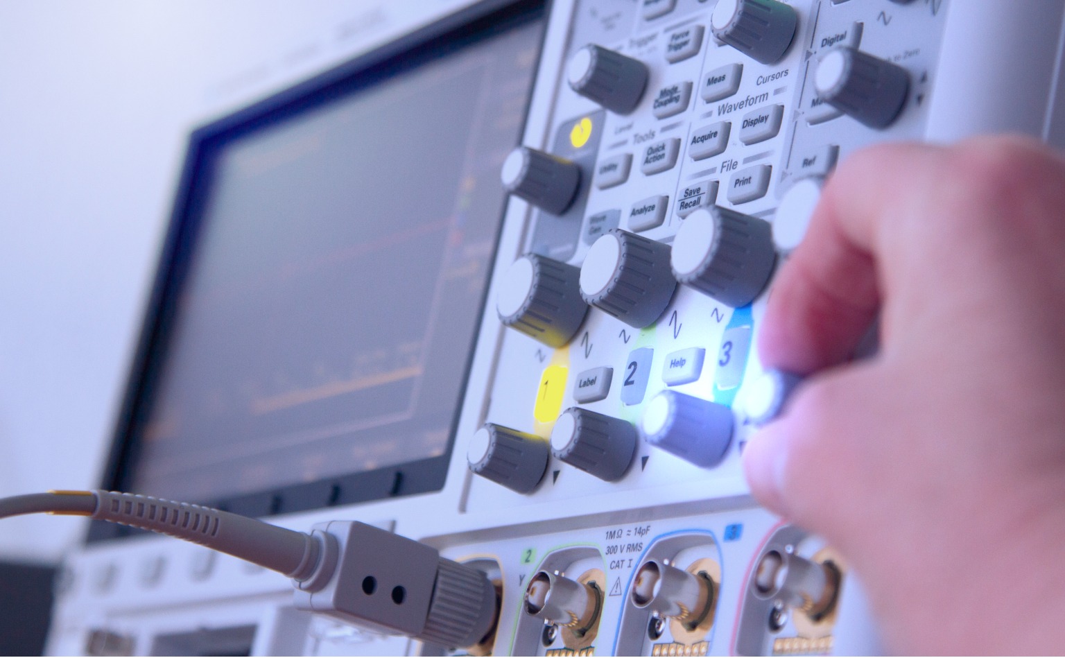
Method 2: Turns‑ratio and oscilloscope method
An alternative when you do not have a high‑quality LCR meter is a turns‑ratio method using an AC source and oscilloscope:
- Drive the primary with a small AC voltage at the operating (or near‑operating) frequency.
- Short the secondary and measure primary current and voltage.
- From the deviation between expected and measured behavior (based on the known turns ratio), infer leakage inductance.
This technique is more involved and requires careful calibration but can be useful when you want to see frequency‑dependent behavior or when fixture parasitics dominate simple LCR readings.
Best Practices for Lab Setups with Planar Transformers
Minimize fixture and lead inductance
Because planar leakage is small, fixture design is part of the measurement. Recommended practices include:
- Use short, twisted pairs or coaxial leads between the transformer and the instrument.
- Avoid long test clips; if you must use them, measure and subtract their inductance.
- Where possible, build a dedicated test PCB with pads that mate to the planar component and short, symmetrical traces to measurement connectors.
Payton’s development teams frequently use socket‑style test boards for their planar transformers and inductors to keep fixture parasitics repeatable and well characterized, especially when validating new designs for harsh environments.
Choose appropriate test frequency and amplitude
Low‑frequency measurements (e.g., 100 Hz or 1 kHz) may be useful for basic characterization, but they do not always reflect behavior at 100-500 kHz or beyond, where many planar transformers operate. To improve relevance:
- Select a test frequency within one decade of the intended operating frequency when possible.
- Use moderate test amplitudes that keep the core in its linear region: large signals can distort both magnetizing and leakage inductance.
- If your instrument allows, sweep frequency to observe any resonances or unexpected capacitance effects.
Payton’s planar design guides emphasize that high‑frequency behavior is where planar magnetics shine, so measurement setups should reflect that reality.
Accounting for Parasitics and Non‑Ideal Effects
Separating leakage from winding resistance and capacitance
Real windings have series resistance and interwinding capacitance. At higher test frequencies, these can affect the apparent inductance measured by an LCR meter. To mitigate this:
- Use series‑inductance (Ls) measurement mode rather than parallel models where applicable.
- Keep test frequency low enough that parasitic capacitance has not yet significantly altered the impedance curve, but high enough to be relevant.
- Where needed, model the transformer in a simulator (SPICE or similar) and fit measured data to extract leakage, resistance, and capacitance separately.
For planar magnetics, this modeling is particularly valuable because the layer geometry is known and repeatable, which aligns well with analytical and FEM‑based leakage models from the literature.
Measuring leakage on multi‑winding and interleaved structures
Many of Payton’s planar designs use interleaved primaries and secondaries and multiple outputs. In such cases, you may want leakage between specific winding pairs, not just “primary vs everything else”. Best practices include:
- Short all non‑measured windings together and to the reference side when measuring leakage between two specific windings.
- Document the exact shorting configuration, since it changes the measured value.
- For integrated resonant transformers, measure both the “baseline” leakage and the effective leakage used as resonant inductance.
This level of discipline aligns with how Payton presents leakage and coupling data in its planar magnetics datasheet guide.
Practical Comparison: Planar vs Conventional Leakage Measurement
Why conventional habits fail on planar parts
Engineers used to conventional transformers sometimes apply the same test habits to planar parts, with mixed results. The table below summarizes key differences:
| Aspect | Planar Transformer | Conventional Transformer |
|---|---|---|
| Typical leakage level | ~0.1-0.5% of primary inductance | ~2-5% of primary inductance |
| Sensitivity to fixtures | High (parasitics comparable to leakage) | Moderate |
| Need for custom test PCB | Often recommended | Usually optional |
| Frequency dependency | Significant at 100 kHz+ | Often measured at 50/60 Hz only |
| Modeling alignment | Excellent (geometry precisely known) | Good but more variation |
Payton’s own experience, reflected in its engineering content, underscores that planar leakage can be a designed‑in feature (for resonant topologies) or minimized aggressively; in both cases, accurate measurement is essential to confirm that reality matches the CAD model.
How Payton Approaches Leakage Inductance in Planar Designs
From simulation to lab correlation
In many custom projects, Payton starts with analytical and FEM‑based leakage predictions for a proposed planar geometry. Those predictions drive:
- Layer stacking and interleaving choices.
- Decisions about whether to integrate resonant inductance.
- Trade‑offs between leakage, capacitance, and EMI behavior.
Once prototypes are built, precision lab measurements (using dedicated fixtures and impedance analyzers) are used to correlate the model with the real component. Any deviation informs the next design iteration or the final datasheet values presented to customers, as outlined in the planar datasheet metrics guide.
Leakage as a controllable design parameter
Rather than treating leakage as an unwanted byproduct, Payton treats it as a controllable design parameter:
- For hard‑switched converters, leakage is minimized using tight coupling and interleaving.
- For LLC and other resonant converters, a precise amount of leakage is targeted to match resonant tank requirements.
- For EMI‑sensitive designs, leakage and capacitance are balanced, sometimes with additional planar inductors used for filtering.
This mindset is why precise measurement is so important: it closes the loop between intention and implementation.
Conclusion: Turning Leakage Measurement into a Design Asset
Accurate leakage inductance measurement is not just a checkbox on a test report; it is a key enabler for sophisticated planar transformer design. When you treat the lab setup: fixtures, frequency, amplitude, and parasitic modeling - with the same care you devote to PCB layout, the resulting data feeds directly into better resonant tanks, cleaner clamp networks, and more predictable EMI behavior.
For teams working with high‑density planar magnetics, especially those co‑designing transformers and inductors with Payton, it is worth formalizing leakage measurement as part of the design workflow, using the company’s planar transformer design guides and datasheet metrics as reference points for both modeling and validation.