Planar vs. Conventional Transformers: Is the NRE Really Worth It?
Understanding the Real Question: Cost vs. Value
 Every time a team considers moving from a conventional wire‑wound transformer to a planar transformer, the same tension appears higher upfront NRE and tooling on one side, better power density, efficiency and repeatability on the other. For project managers, the question is not purely technical. It is budgetary, strategic, and scheduled.
Planar designs typically involve custom cores, PCB or leadframe tooling, and a closer collaboration phase with a specialist manufacturer. Conventional designs, by contrast, can often be sourced from existing platforms or modified with relatively low engineering overhead. To make a defensible choice, you need a structured way to compare both paths across the full product lifecycle, not just the first quote.
This article walks through a “spreadsheet‑style” cost‑benefit analysis that you can implement directly in Excel or your preferred planning tool, using the technical realities described in Payton’s planar vs. conventional transformer overview and the broader planar transformer guides.
Core Differences That Drive Cost
Height, Power Density and PCB Real Estate
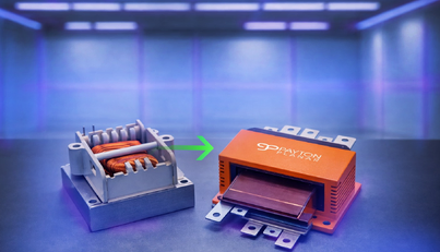
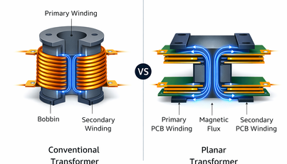
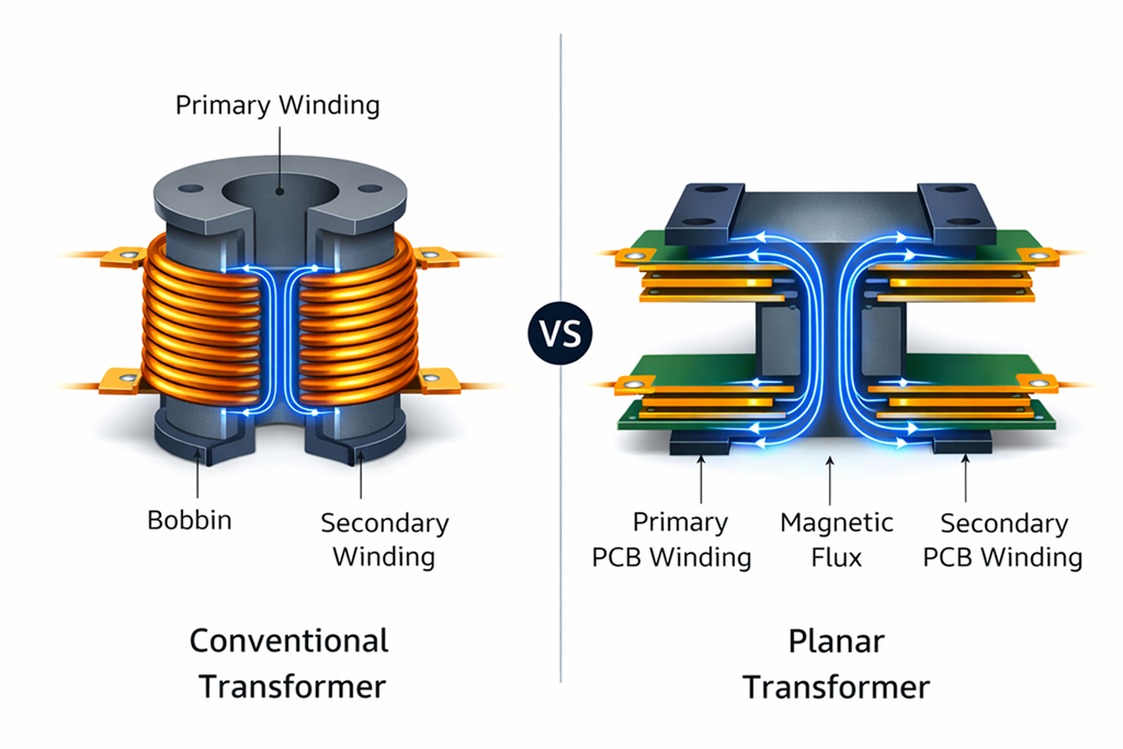
Planar transformers are inherently low‑profile because their windings are implemented as PCB traces or flat copper instead of bulky wound coils on tall bobbins. This makes them ideal when enclosure height is constrained: medical devices, automotive converters, and high‑density power supplies are typical examples.
In addition, planar magnetic designs can achieve significantly higher power density, with Payton noting that planar transformers can deliver up to around three times the power density of conventional equivalents in some applications. In practical terms, higher power density and lower height free up PCB area for additional functions, reduce enclosure volume, or allow you to increase output power without redesigning the mechanical envelope.
When you build your spreadsheet, it is useful to assign a notional value to every square centimeter of PCB area and every millimeter of saved height. That way, “performance” becomes a quantified economic factor, not just a technical nice‑to‑have.
Efficiency, Thermal Performance and Reliability
Planar transformers typically offer very good efficiency because their copper geometry is controlled and thermal paths are more predictable. Their flat construction spreads heat across a larger surface area, which can reduce hot‑spot temperatures and improve long‑term reliability.
Studies comparing planar and conventional transformers in resonant converters show that planar designs can achieve lower maximum temperatures and better heat dissipation at comparable or higher power levels. Over a product’s lifetime, even a modest efficiency gain can reduce energy consumption and cooling needs, which is relevant in applications like data centers or 24/7 industrial systems.
In your cost‑benefit sheet, those efficiency and thermal advantages can be converted into:
- Reduced cooling hardware cost.
- Lower field failure risk and warranty exposure.
- Potentially longer service intervals for systems where maintenance is expensive.
Mapping Costs: NRE, Tooling and Unit Price
What Counts as NRE for Planar Transformers?
Moving to planar typically introduces Non‑Recurring Engineering (NRE) that you will not see on a simple catalog conventional part:
- Magnetic design, simulation and optimization.
- PCB or copper leadframe layout and tooling.
- Custom core tooling or adaptation of an existing core family.
Validation for insulation, creepage and partial discharge, especially in high‑voltage designs.
As Payton’s resources point out, planar transformers are often custom‑designed to a specific customer requirement and application space, which concentrates more engineering effort into the front of the project. This is not a sunk cost if your volumes are significant. But at low volumes, it can dominate the business case.
Unit Cost Dynamics at Different Volumes
Conventional wire‑wound transformers usually have:
- Low or zero NRE (especially when adapting an existing platform).
- Higher variability in performance due to winding tolerances.
- A relatively flat unit price reduction curve with volume.
Planar transformers, on the other hand, often start with a higher development cost but benefit from:
- Highly repeatable manufacturing and performance.
- Better suitability for automated production.
- More favorable unit economics at medium‑to‑high volumes.
External comparisons of standard vs planar transformers in battery charger applications highlight that planar introduces higher initial PCB‑related costs (for example, thick multi‑layer boards) but can offer substantially improved power density and competitive efficiency when integrated into an existing multi‑layer power PCB. In such integrated approaches, the high PCB cost is spread over the entire converter instead of being allocated solely to the transformer.
Your spreadsheet should therefore explicitly include:
- NRE total (engineering + tooling)
- Unit cost at low volume (e.g., 100 pcs)
- Unit cost at mid volume (e.g., 1,000–5,000 pcs)
- Unit cost at high volume (e.g., 10,000+ pcs)
Building A Spreadsheet‑Style Cost‑Benefit Model
Step 1: Define Your Project Parameters
Start by listing the project assumptions that influence both cost and benefit:
- Target power level and topology.
- Annual production volume and expected product lifetime.
- Available height and footprint.
- Efficiency targets and allowable losses.
- Compliance requirements (medical, automotive, industrial, high‑voltage).
You can use Payton’s Planar “Transitioning from Conventional to Planar Transformers” guide as a technical checklist when moving from a conventional to a planar concept. This helps ensure that the assumptions you enter your sheet reflect realistic magnetic designs rather than idealized numbers.
Step 2: Capture Cost Inputs for Both Options
Create two adjacent columns in your spreadsheet: “Conventional” and “Planar”. For each line item, enter either a numeric value or a range:
- NRE engineering cost.
- Tooling and validation cost.
- Prototype and sample cost.
- Unit cost at defined volumes.
- Expected production yield.
- Estimated cooling hardware cost (heatsinks, fans, thermal interface materials).
Where information is not yet available, use ranges or best‑guess values and clearly flag them. This also makes it easier to run sensitivity analyses later.
Step 3: Quantify Benefits and Hidden Costs
Next, create a section for benefits and “hidden costs” that are not always captured on a component quote:
- PCB area saved (cm²) and its notional cost.
- Enclosure volume and height saved, if this avoids mechanical redesign or enables higher power variants.
- Efficiency gains (percentage points), which can be converted into kWh saved over product lifetime.
- Reduced assembly time or simplified manufacturing steps due to planar construction and automation.
- Expected reduction in field failures or warranty claims due to better thermal performance and repeatable parasitics.
For example, if planar enables you to avoid a second PCB or a larger mechanical enclosure, assign an actual cost to those avoided items in your spreadsheet. This often has more impact than the transformer price difference alone.
When Planar Clearly Pays Off (and when it doesn’t)
High Volume and Platform Designs
Planar is most compelling when:
- Volumes are medium to high.
- The transformer design will be reused across multiple products.
- You are already committed to a multi‑layer power PCB.
In those scenarios, the NRE is spread over many units, and the benefits (higher power density, better thermal performance, improved efficiency) directly contribute to platform value and product differentiation. Over time, the effective cost per unit (including NRE amortization) can be lower than staying with a conventional approach, especially when you consider reduced assembly effort and improved field reliability.
Low Volume, Niche or Time‑Critical Projects
Conversely, planar may be harder to justify when:
- Volumes are low or uncertain.
- Time‑to‑market is extremely tight.
- The design is likely to change frequently after launch.
In such cases, the simplicity and flexibility of a conventional transformer can outweigh the performance gains of planar. Rewinding or slightly modifying a conventional design is often faster and cheaper than respinning a PCB‑based planar magnetics structure, particularly if each iteration demands new tooling.
For project managers, the key is not to label one technology “better” than the other. Instead, use the structured spreadsheet model to show stakeholders exactly where the break‑even point lies for your specific project.
Where Payton Adds Unique Value Beyond Standard Planar
Most planar magnetics suppliers stop at "build to spec," but Payton differentiates through deep co-design that aligns the magnetic component directly with your converter topology from the ground up. Rather than treating the transformer as an off-the-shelf part, Payton's engineers collaborate on topology-specific optimization, whether you're running an LLC resonant converter, phase-shifted full-bridge, or active clamp flyback. For example, in LLC designs, they precisely control leakage inductance (typically 10-100 μH) by adjusting layer spacing and interleaving patterns, eliminating the need for a separate resonant inductor and saving 20-30% board space. This isn't guesswork; it's backed by FEM simulation and prototype validation to hit your exact magnetizing inductance ratio (Lm/Lr) targets.
Payton's sweet spot is high-frequency operation from 200 kHz to 1 MHz, where we excel at multi-layer interleaving (up to 24 layers) and copper foil optimization (70-200 μm thick) to balance skin/proximity losses while maximizing coupling (k > 0.995). Our high‑power planar transformers routinely handle 200-1000W at these frequencies with <1% inductance tolerance, and demonstrated controlled leakage for resonant topologies that supports ZVS/ZCS operation with minimal added EMI. The integrated thermal path is another hallmark: copper planes and via arrays create 0.5-2 W/K conductance directly into the host PCB, spreading heat predictably without external heatsinks in many <1 kW designs.
For defense and aerospace, where manufacturing repeatability is non‑negotiable, Payton's automated processes deliver ±0.5% part-to-part variation across production runs of 10,000+ units: qualified to AEC‑Q200, EEE-INST-002, and Mil-Std-981 with partial discharge testing up to 20 kVrms. This level of precision and harsh‑environment ruggedness (vibration, thermal cycling, radiation tolerance) makes our planar magnetics the go-to for mission-critical avionics, radar power, and satellite converters, where even 1% drift can mean failure. By combining topology co-design, high-frequency mastery, and bulletproof repeatability, Payton doesn't just supply magnetics, we engineer system‑level wins that generic suppliers can't match.
Using Payton Resources to De‑Risk the Decision
For organizations evaluating planar for the first time, it helps to ground your spreadsheet inputs in real‑world experience rather than purely theoretical numbers. Here, at Payton Group, we published several resources that can inform your model:
- A dedicated page on planar vs. conventional transformers that outlines differences in design, size, efficiency and safety.
- Engineering guidance on moving from conventional to planar transformers, covering core selection, PCB windings and thermal considerations.
- A broader planar transformer guide that discusses cost considerations, applications and design challenges.
- Application examples of high‑power planar transformers, such as a 6.5 kW high‑voltage planar transformer designed for reliable, high‑frequency power conversion.
Referencing these materials as you populate your spreadsheet will help keep your assumptions realistic and aligned with what is achievable in production.
Conclusion: One Clear Next Step for Your Project
Planar magnetics do not automatically make financial sense for every project, but they can decisively improve the economics of the right ones. The difference lies in whether you treat them as a line‑item cost or as a design lever that affects size, efficiency, reliability and long‑term platform strategy.
The most practical next step is to build a simple two‑column spreadsheet (conventional vs. planar) using your real project parameters, then review it with your magnetics partner to refine NRE, volume pricing and performance assumptions before you lock in a decision.