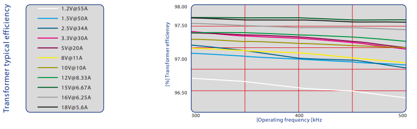
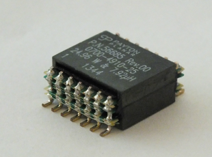
100W SMT standard transformers
Key Specifications
 Input voltage of power stage: 18 - 36 Vdc link.
- Power Range: up to 100W.
- Topology: Forward with resonant reset or active clamp
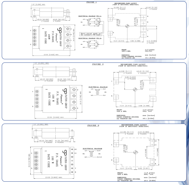
- Footprint: 23.5mm x 20.1mm - Max.
- Height: 7.4mm - Max.
- Frequency range: 300 kHz to 500 kHz.
- Pri./Sec. isolation (operational): 1800 Vdc.
- Operating ambient temperature: -40°C to +85°C.
Electrical Specifications@25°C
| Part Number | Fig. | Output Voltage & Current | Primary Side | Secondary Side | Turns Ratio | Duty Cycle Max. | Pri. to Sec. Capacitance Max. [pF] | ||||
|---|---|---|---|---|---|---|---|---|---|---|---|
| Number of Turns | Inductance Nominal [µH] | Leak. Ind. Maximum [µH] | DCR Max. [mΩ] | Number of Turns | DCR Max. [mΩ] | ||||||
| 50465 | 1a | 1.2V@55A- 1.5V@50A | 6 | 79 | 0.15 | 10 | 1//1 | 0.5//0.5 | 6:1:1 | 0.686 | 150 |
| 50465 | 1b | 2.5V@34A- 3.3V@30A | 6 | 79 | 0.15 | 10 | 1+1 | 0.5+0.5 | 6:1:1 | 0.651 | 150 |
| 50466 | 2 | 5.0V@20A | 6 | 79 | 0.15 | 10 | 3 | 2.4 | 6:3 | 0.629 | 150 |
| 50467 | 3 | 8.0V@11A- 10.0V@10A | 6 | 79 | 0.15 | 10 | 6 | 16 | 6:6 | 0.60 | 200 |
| 50468 | 3 | [email protected] [email protected] | 6 | 79 | 0.1 | 10 | 8 | 22 | 6:8 | 0.664 | 250 |
| 50469 | 3 | [email protected] [email protected] | 6 | 79 | 0.1 | 10 | 10 | 30 | 6:10 | 0.634 | 250 |
| 50807 | 3 | 9V@11A | 6 | 79 | 10 | 0.15 | 5 | 9 | 6:5 | 0.65 | 200 |
1. The Transformer has to be attached to a Heat Sink (PCB with Aluminum substrate) with a maximum 85°C temperature.
2. The Transformer hot spot temperature can be calculated as: Thotspot = Theatsink + 20 x Plosses [W].
Mechanical Specifications and Electrical diagrams
Key Specifications
- Input voltage of power stage: 36 - 75 Vdc link.
- Power Range: up to 100W.
- Topology: Forward with resonant reset or active clamp
- Footprint: 23.5mm x 20.1mm - Max.
- Height: 7.4mm - Max.
- Frequency range: 300 kHz to 500 kHz.
- Pri./Sec. isolation (operational): 1800 Vdc.
- Operating ambient temperature: -40°C to +85°C.
Electrical Specifications@25°C
| Part Number | Fig. | Output Voltage & Current | Primary Side | Secondary Side | Turns Ratio | Duty Cycle Max. | Pri. to Sec. Capacitance Max. [pF] | ||||
|---|---|---|---|---|---|---|---|---|---|---|---|
| Number of Turns | Inductance Nominal [µH] | Leak. Ind. Maximum [µH] | DCR Max. [mΩ] | Number of Turns | DCR Max. [mΩ] | ||||||
| 50460 | 1a | 1.2V@55A- 1.5V@50A | 12 | 316 | 0.8 | 40 | 1//1 | 0.5//0.5 | 12:1:1 | 0.642 | 150 |
| 50460 | 1b | 2.5V@34A- 3.3V@30A | 12 | 316 | 0.8 | 40 | 1+1 | 0.5+0.5 | 12:1:1 | 0.642 | 150 |
| 50461 | 2 | 5.0V@20A | 12 | 316 | 0.6 | 40 | 3 | 2.4 | 12:3 | 0.62 | 150 |
| 50462 | 3 | 8.0V@11A- 10.0V@10A | 12 | 316 | 0.3 | 40 | 6 | 16 | 12:6 | 0.592 | 200 |
| 50463 | 3 | [email protected] [email protected] | 12 | 316 | 0.25 | 40 | 8 | 22 | 12:8 | 0.655 | 250 |
| 50464 | 3 | [email protected] [email protected] | 12 | 316 | 0.25 | 40 | 10 | 30 | 12:10 | 0.625 | 250 |
1. The Transformer has to be attached to a Heat Sink (PCB with Aluminum substrate) with a maximum 85°C temperature.
2. The Transformer hot spot temperature can be calculated as: Thotspot = Theatsink + 20 x Plosses [W].